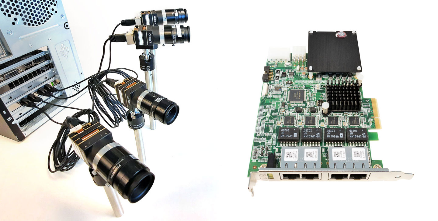
ADLINK’s PCIe-GIE72/74 is a PCI ExpressR x4 lane, GigE Vision PoE+ (Power Over Ethernet Plus) network interface card that supports 2/4CH independent Gigabit Ethernet ports for multiple GigE Vision device connections with data transfer up to 1 Gb/s per port. The following instructions describe how ADLINK Smart GigE Tool is used to send Action Commands to software trigger LUCID cameras and display in ArenaView.
System Specifications
- Windows 10 Pro 64-bit, version 2004, Build 19041.867
- ADLINK Smart GigE Tool, GiE Version:1.5.5.0315 (Driver: 1.2.3.0320, Library: 1.3.5.0315, GIGE Tool: 1.2.5.0324)
Prerequisites
Install the ADLINK Ethernet network interface card into your computer and connect all your LUCID cameras to the card. The card supports PoE but to make sure you have adequate power for all cameras please connect the auxiliary power connector (from your PC power supply) to the internal AUX power supply port on the interface card.
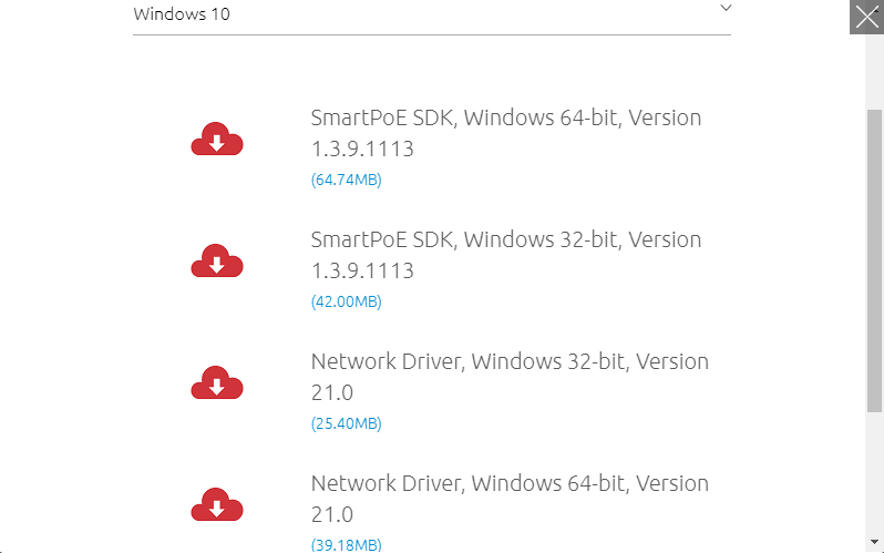
Make sure you have downloaded and installed:
- PCle-GIE72/74 PRO SmartPoE SDK (execute .exe as administrator)
- PCle-GIE 72/74 PRO Network Driver (Intel I120 LAN driver)
Ethernet IP Address Set up
Assign proper TCP/IP for each PCIe-GIE7x LAN port. (Intel I210 Gigabit Network Connection).
Control Panel -> Network and Internet-> Network and Sharing Center -> Change Adapter setting -> Properties -> Internet Protocol Version 4 (TCP/IPv4) Properties
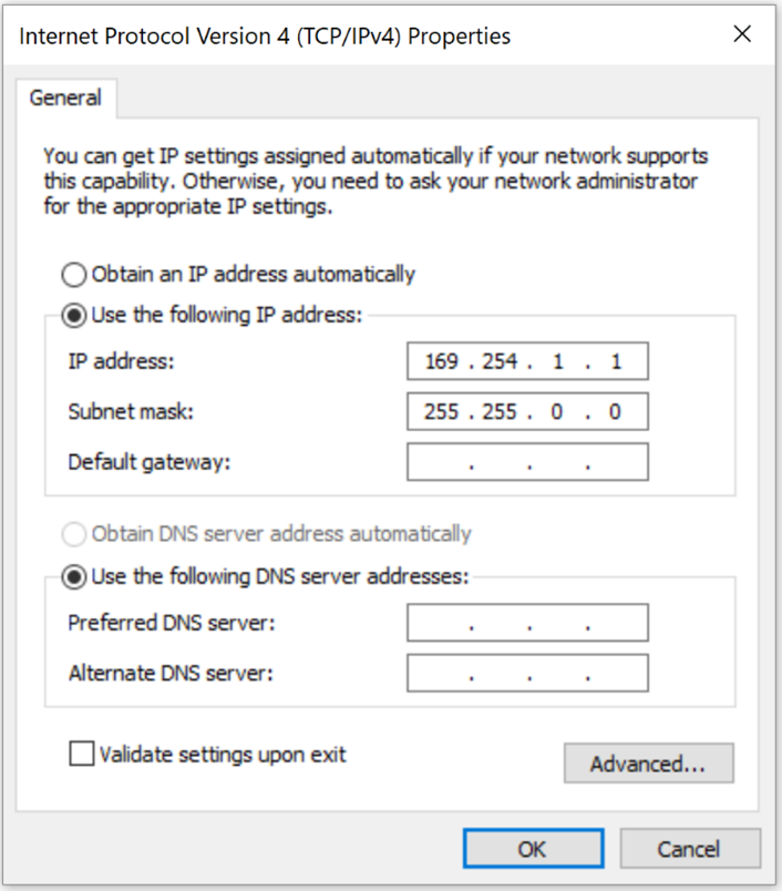
(Camera IP set to 169.254.1.1)
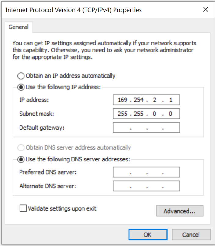
(Camera IP set to 169.254.2.1)
Camera IP Address Setup
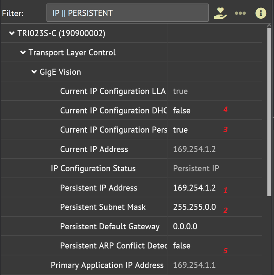
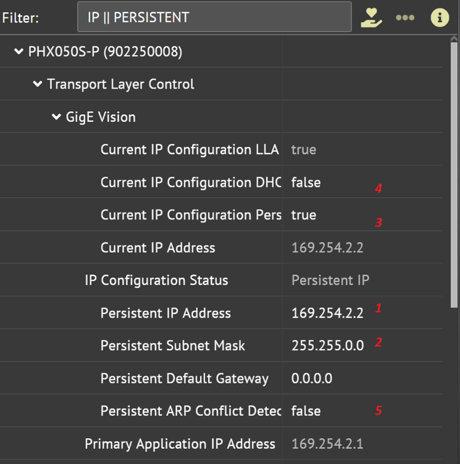
Assign proper persistent IP addresses for each camera in Arena in the following order as shown below:
- Assign proper GevPersistentIPAddress and GevPersistentSubnetMask.
- Set GevCurrentIPConfigurationPersistentIP flag to true, GevCurrentIPConfigurationDHCP flag to false, and GevPersistentARPConflictDetectionEnable to false.
- Power cycle the camera.
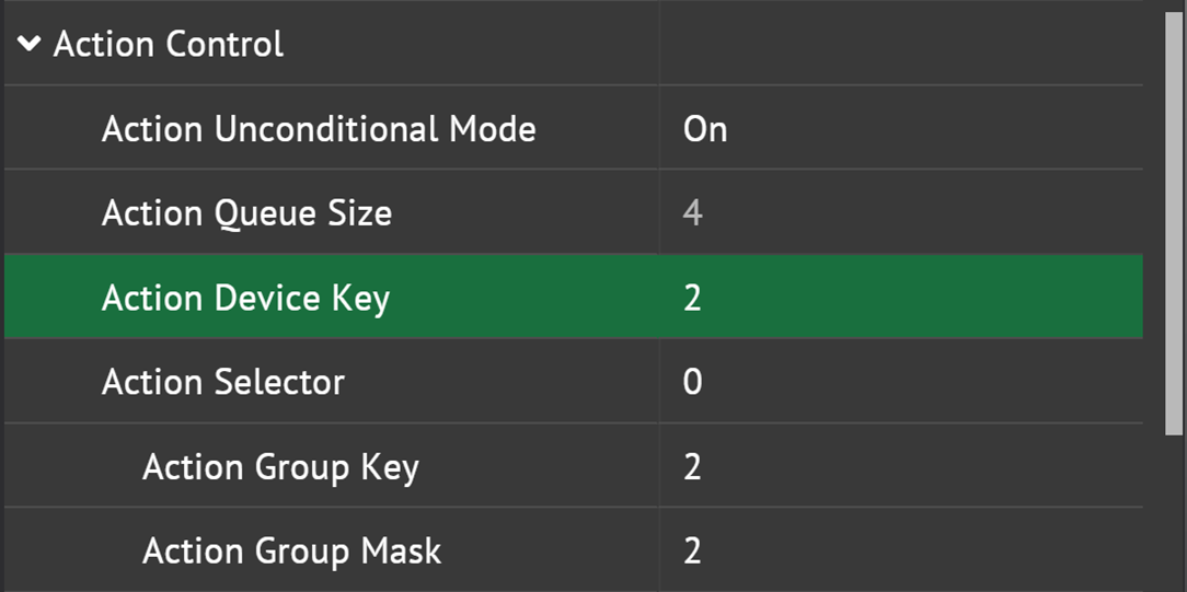
Camera ToE Parameter Setup
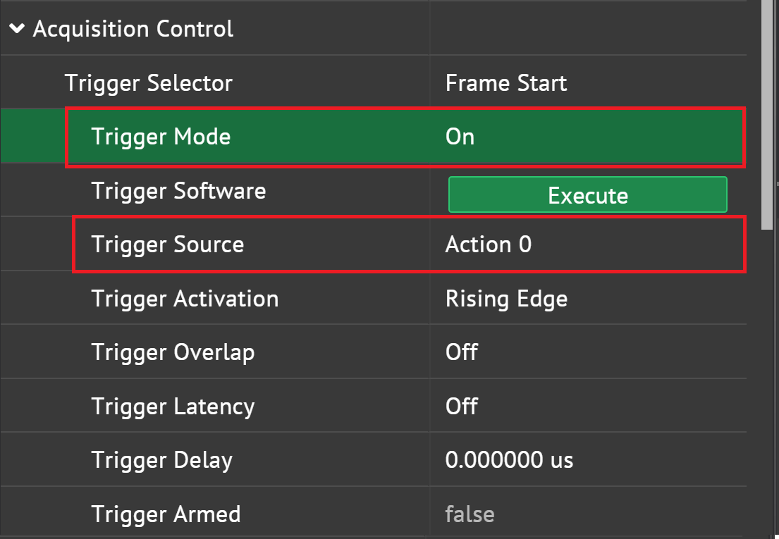
Set TriggerMode to On, and TriggerSource to Action 0 on all cameras:
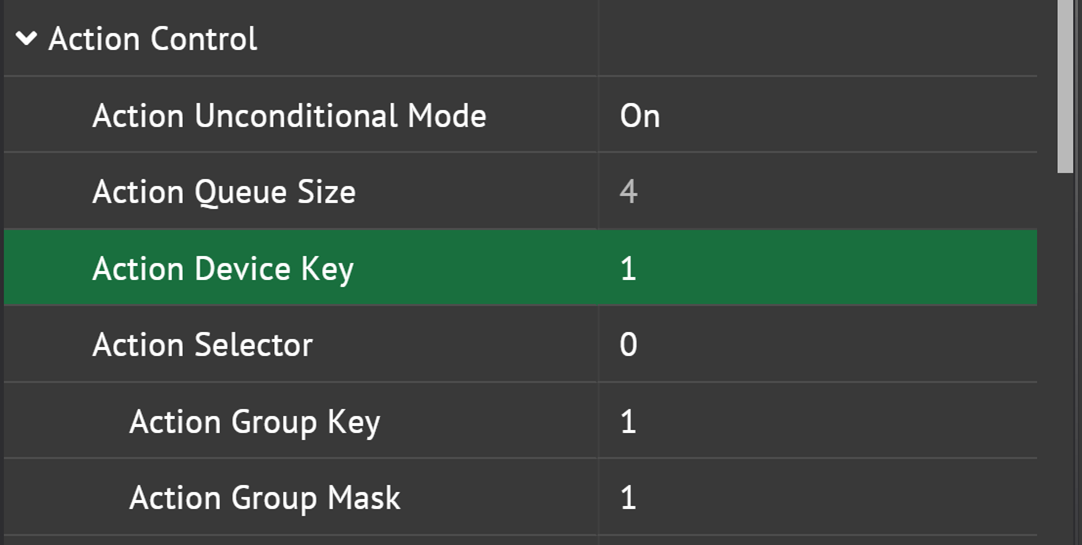
- Set Action Unconditional Mode On
- Assign device key, group key, group mask for each camera.
Start Streaming
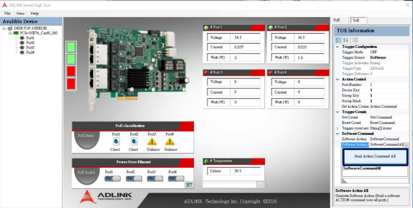
Using ADLINK Smart GigE Tool
Located: C:\Program Files\ADLINK\GIE Series\GigE Tool
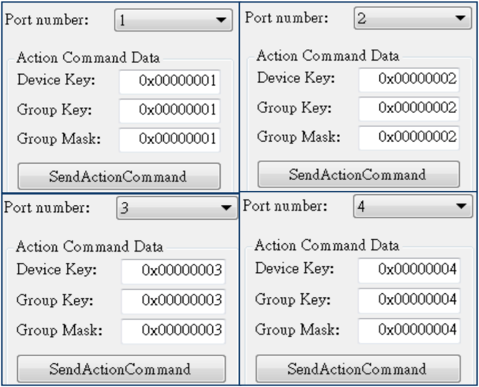
Set up the ToE parameter.
- Set > Device Key > Group Key > Group Mask
- Set Action Command for each port:
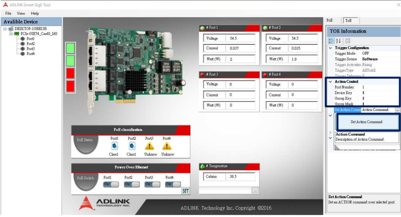
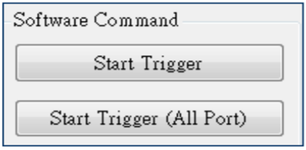
Trigger camera in ADLINK Smart GigE Tool then check the image acquisition on ArenaView.
Using ToE Samples
Located: C:\Program Files\ADLINK\GIE Series\Samples\ToE Samples\VC\x64\Release
Set up the ToE parameter.
- Set > Device Key > Group Key > Group Mask
- Set Action Command for each port:
Trigger camera in ToE samples then check the image acquisition on ArenaView.
For more information on ADLINK’s PCle-GIE72/74 PRO with Trigger Over Ethernet (ToE), please visit the ADLINK product page