• Support Home
  • Getting Started
    • Connecting Your Camera
    • 3rd Party Software Getting Started Guides
  • Tech Ref Manuals
    • Arena SDK Documentation
    • HTP003S – Helios2+ ToF 3D
    • HLT003S – Helios2 ToF 3D
    • HLS003S – Helios ToF 3D
    • HLF003S – Helios Flex ToF 3D
    • ATX245S – Atlas10 24.5 MP
    • ATX204S – Atlas10 20.4 MP
    • ATX162S – Atlas10 16.2 MP
    • ATX124S – Atlas10 12.3 MP
    • ATX081S – Atlas10 8.1 MP
    • ATX051S – Atlas10 5.0 MP
    • ATL314S – Atlas 31.4 MP
    • ATL196S – Atlas 19.6 MP
    • ATL168S – Atlas 16.8 MP
    • ATL120S – Atlas 12.3 MP
    • ATL089S – Atlas 8.9 MP
    • ATL071S – Atlas 7.1 MP
    • ATL050S – Atlas 5.0 MP
    • ATL028S – Atlas 2.8 MP
    • ATP200S – Atlas IP67 20 MP
    • ATP120S – Atlas IP67 12.3 MP
    • ATP089S -Atlas IP67 8.9 MP
    • ATP071S – Atlas IP67 7.1 MP
    • ATP028S – Atlas IP67 2.8 MP
    • TRI200S – Triton 20.0 MP
    • TRI120S – Triton 12.3 MP
    • TRI122S – Triton 12.2 MP
    • TRI089S – Triton 8.9 MP
    • TRI071S – Triton 7.1 MP
    • TRI064S – Triton 6.3 MP
    • TRI054S – Triton 5.4 MP
    • TRI050S-P/Q – Triton 5.0 MP Polarized
    • TRI050S – Triton 5.0 MP
    • TRI032S – Triton 3.2 MP
    • TRI028S – Triton 2.8 MP
    • TRI023S – Triton 2.3 MP
    • TRI016S – Triton 1.6 MP
    • TRI004S – Triton 0.4 MP
    • TRI02KA – Triton 2K Line Scan
    • PHX200S – Phoenix 20.0 MP
    • PHX120S – Phoenix 12.3 MP
    • PHX122S – Phoenix 12.2 MP
    • PHX089S – Phoenix 8.9 MP
    • PHX064S – Phoenix 6.3 MP
    • PHX050S-P/Q – Phoenix 5.0 MP Polarized
    • PHX050S – Phoenix 5.0 MP
    • PHX032S – Phoenix 3.2 MP
    • PHX023S – Phoenix 2.3 MP
    • PHX016S – Phoenix 1.6 MP
    • PHX004S – Phoenix 0.4 MP
  • Application Notes
    • Bandwidth Sharing in Multi-Camera Systems
    • Combine Helios 3D Point Cloud with RGB Color
    • I2C Support on LUCID Cameras
    • Using GPIO on LUCID Cameras
    • Using PTP & Scheduled Action Commands
    • Helios2 And Triton Synchronization
  • Knowledge Base
  • Additional Support
    • Product Change Notifications (PCN)
    • Contact Support
  • Log In
  • Support Home
  • Getting Started
    • Connecting Your Camera
    • 3rd Party Software Getting Started Guides
  • Tech Ref Manuals
    • Arena SDK Documentation
    • HTP003S – Helios2+ ToF 3D
    • HLT003S – Helios2 ToF 3D
    • HLS003S – Helios ToF 3D
    • HLF003S – Helios Flex ToF 3D
    • ATX245S – Atlas10 24.5 MP
    • ATX204S – Atlas10 20.4 MP
    • ATX162S – Atlas10 16.2 MP
    • ATX124S – Atlas10 12.3 MP
    • ATX081S – Atlas10 8.1 MP
    • ATX051S – Atlas10 5.0 MP
    • ATL314S – Atlas 31.4 MP
    • ATL196S – Atlas 19.6 MP
    • ATL168S – Atlas 16.8 MP
    • ATL120S – Atlas 12.3 MP
    • ATL089S – Atlas 8.9 MP
    • ATL071S – Atlas 7.1 MP
    • ATL050S – Atlas 5.0 MP
    • ATL028S – Atlas 2.8 MP
    • ATP200S – Atlas IP67 20 MP
    • ATP120S – Atlas IP67 12.3 MP
    • ATP089S -Atlas IP67 8.9 MP
    • ATP071S – Atlas IP67 7.1 MP
    • ATP028S – Atlas IP67 2.8 MP
    • TRI200S – Triton 20.0 MP
    • TRI120S – Triton 12.3 MP
    • TRI122S – Triton 12.2 MP
    • TRI089S – Triton 8.9 MP
    • TRI071S – Triton 7.1 MP
    • TRI064S – Triton 6.3 MP
    • TRI054S – Triton 5.4 MP
    • TRI050S-P/Q – Triton 5.0 MP Polarized
    • TRI050S – Triton 5.0 MP
    • TRI032S – Triton 3.2 MP
    • TRI028S – Triton 2.8 MP
    • TRI023S – Triton 2.3 MP
    • TRI016S – Triton 1.6 MP
    • TRI004S – Triton 0.4 MP
    • TRI02KA – Triton 2K Line Scan
    • PHX200S – Phoenix 20.0 MP
    • PHX120S – Phoenix 12.3 MP
    • PHX122S – Phoenix 12.2 MP
    • PHX089S – Phoenix 8.9 MP
    • PHX064S – Phoenix 6.3 MP
    • PHX050S-P/Q – Phoenix 5.0 MP Polarized
    • PHX050S – Phoenix 5.0 MP
    • PHX032S – Phoenix 3.2 MP
    • PHX023S – Phoenix 2.3 MP
    • PHX016S – Phoenix 1.6 MP
    • PHX004S – Phoenix 0.4 MP
  • Application Notes
    • Bandwidth Sharing in Multi-Camera Systems
    • Combine Helios 3D Point Cloud with RGB Color
    • I2C Support on LUCID Cameras
    • Using GPIO on LUCID Cameras
    • Using PTP & Scheduled Action Commands
    • Helios2 And Triton Synchronization
  • Knowledge Base
  • Additional Support
    • Product Change Notifications (PCN)
    • Contact Support
  • Log In
home/Knowledge Base/Camera Features/Binning and Decimation on LUCID Cameras

Binning and Decimation on LUCID Cameras

1695 views 9 November 20, 2020 Updated on December 2, 2020

Binning

Binning is where columns and/or rows of pixels are combined to achieve a reduced overall image size without changing the image’s field of view. This feature may result in an increase of camera’s frame rate.
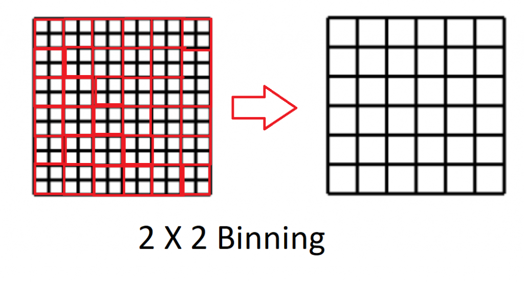
The binning factor indicates how many pixels in the horizontal and vertical axis are combined. For example, when applying 2×2 binning, which is 2 pixels in the horizontal axis and 2 pixels in the vertical axis, 4 pixels combine to form 1 pixel.
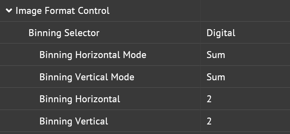
There are two types of binning: Sensor binning or Digital binning

  • Sensor binning is binning performed on the sensor
  • Digital binning is binning performed on the FPGA

There are two methods of binning:

  • Summation (additive) binning is when multiple pixels combine to form 1 pixel by summing pixels. This method will result in brighter images.
  • Average binning is when multiple pixels combine to form 1 pixel by averaging pixels. This method can result in less noisy images.

Most color sensors do not support sensor binning since Bayer patterns will need to be taken consideration. Instead they will have digital binning performed on FPGA. Binning is not supported in in color processed pixel formats like BGR8 and RGB8.

When binning is used, the settings of the image width and height will be affected. For example, if you are using a camera with sensor resolution of 2448 x 2048 and apply 2×2 binning, the effective resolution of the resultant image is reduced to 1224 x 1024. This can be verified by checking the Width and Height nodes.

When horizontal decimation is used, horizontal binning (if supported) is not available. When vertical decimation is used, vertical binning (if supported) is not available.

Decimation

Decimation is in which columns and/or rows of pixel are skipped to achieve reduced overall image size without changing the image’s field of view. This feature is also known as “subsampling” due to the smaller sample size of pixels the camera transmits. This feature may result in an increase of camera’s frame rate.
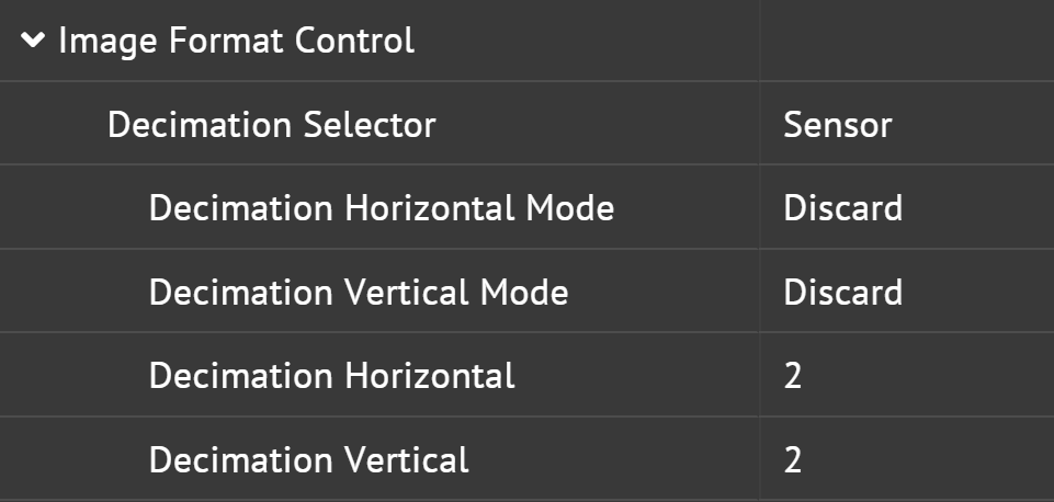
When decimation is used, the settings of the image width and height will be affected. For Example, if you are using a camera with sensor resolution 2448 x 2048. When horizontal and vertical decimation are both set to 2, the effective resolution of the resultant image is reduced to 1224 x 1024. This can be verified by checking the Width and Height nodes.

When horizontal binning is used, horizontal decimation (if supported) is not available. When vertical binning is used, vertical decimation (if supported) is not available.

Was this helpful?

9 Yes  2 No
Related Articles
  • Using Application Switchover with LUCID Cameras
  • Using Multiple ROIs with LUCID Cameras
  • Unicast Device Discovery with LUCID Cameras
  • Using VLANs with LUCID Cameras
  • Using TCP with Atlas10 cameras on Linux
  • Using TCP with Atlas10 cameras on Windows

Didn't find your answer? Contact Us

  Removing the IR Cut Filter from Color Cameras

Using LUCID’s TFL to EF Lens Controller (Birger Adapter)  

© 2023 LUCID Vision Labs Inc.
Looking to purchase our cameras?
Visit the LUCID Webstore at thinklucid.com