• Support Home
  • Getting Started
    • Connecting Your Camera
    • 3rd Party Software Getting Started Guides
  • Tech Ref Manuals
    • Arena SDK Documentation
    • HTP003S – Helios2+ ToF 3D
    • HLT003S – Helios2 ToF 3D
    • HLS003S – Helios ToF 3D
    • HLF003S – Helios Flex ToF 3D
    • ATX245S – Atlas10 24.5 MP
    • ATX204S – Atlas10 20.4 MP
    • ATX162S – Atlas10 16.2 MP
    • ATX124S – Atlas10 12.3 MP
    • ATX081S – Atlas10 8.1 MP
    • ATX051S – Atlas10 5.0 MP
    • ATL314S – Atlas 31.4 MP
    • ATL196S – Atlas 19.6 MP
    • ATL168S – Atlas 16.8 MP
    • ATL120S – Atlas 12.3 MP
    • ATL089S – Atlas 8.9 MP
    • ATL071S – Atlas 7.1 MP
    • ATL050S – Atlas 5.0 MP
    • ATL028S – Atlas 2.8 MP
    • ATP200S – Atlas IP67 20 MP
    • ATP120S – Atlas IP67 12.3 MP
    • ATP089S -Atlas IP67 8.9 MP
    • ATP071S – Atlas IP67 7.1 MP
    • ATP028S – Atlas IP67 2.8 MP
    • TRI200S – Triton 20.0 MP
    • TRI120S – Triton 12.3 MP
    • TRI122S – Triton 12.2 MP
    • TRI089S – Triton 8.9 MP
    • TRI071S – Triton 7.1 MP
    • TRI064S – Triton 6.3 MP
    • TRI054S – Triton 5.4 MP
    • TRI050S-P/Q – Triton 5.0 MP Polarized
    • TRI050S – Triton 5.0 MP
    • TRI032S – Triton 3.2 MP
    • TRI028S – Triton 2.8 MP
    • TRI023S – Triton 2.3 MP
    • TRI016S – Triton 1.6 MP
    • TRI005S – Triton 0.5 MP
    • TRI004S – Triton 0.4 MP
    • TRI02KA – Triton 2K Line Scan
    • PHX200S – Phoenix 20.0 MP
    • PHX120S – Phoenix 12.3 MP
    • PHX122S – Phoenix 12.2 MP
    • PHX089S – Phoenix 8.9 MP
    • PHX064S – Phoenix 6.3 MP
    • PHX050S-P/Q – Phoenix 5.0 MP Polarized
    • PHX050S – Phoenix 5.0 MP
    • PHX032S – Phoenix 3.2 MP
    • PHX023S – Phoenix 2.3 MP
    • PHX016S – Phoenix 1.6 MP
    • PHX004S – Phoenix 0.4 MP
  • Application Notes
    • Bandwidth Sharing in Multi-Camera Systems
    • Combine Helios 3D Point Cloud with RGB Color
    • I2C Support on LUCID Cameras
    • Using GPIO on LUCID Cameras
    • Using PTP & Scheduled Action Commands
    • Helios2 And Triton Synchronization
    • Product Change Notifications (PCN)
  • Knowledge Base
  • Contact Support
  • Log In
  • Support Home
  • Getting Started
    • Connecting Your Camera
    • 3rd Party Software Getting Started Guides
  • Tech Ref Manuals
    • Arena SDK Documentation
    • HTP003S – Helios2+ ToF 3D
    • HLT003S – Helios2 ToF 3D
    • HLS003S – Helios ToF 3D
    • HLF003S – Helios Flex ToF 3D
    • ATX245S – Atlas10 24.5 MP
    • ATX204S – Atlas10 20.4 MP
    • ATX162S – Atlas10 16.2 MP
    • ATX124S – Atlas10 12.3 MP
    • ATX081S – Atlas10 8.1 MP
    • ATX051S – Atlas10 5.0 MP
    • ATL314S – Atlas 31.4 MP
    • ATL196S – Atlas 19.6 MP
    • ATL168S – Atlas 16.8 MP
    • ATL120S – Atlas 12.3 MP
    • ATL089S – Atlas 8.9 MP
    • ATL071S – Atlas 7.1 MP
    • ATL050S – Atlas 5.0 MP
    • ATL028S – Atlas 2.8 MP
    • ATP200S – Atlas IP67 20 MP
    • ATP120S – Atlas IP67 12.3 MP
    • ATP089S -Atlas IP67 8.9 MP
    • ATP071S – Atlas IP67 7.1 MP
    • ATP028S – Atlas IP67 2.8 MP
    • TRI200S – Triton 20.0 MP
    • TRI120S – Triton 12.3 MP
    • TRI122S – Triton 12.2 MP
    • TRI089S – Triton 8.9 MP
    • TRI071S – Triton 7.1 MP
    • TRI064S – Triton 6.3 MP
    • TRI054S – Triton 5.4 MP
    • TRI050S-P/Q – Triton 5.0 MP Polarized
    • TRI050S – Triton 5.0 MP
    • TRI032S – Triton 3.2 MP
    • TRI028S – Triton 2.8 MP
    • TRI023S – Triton 2.3 MP
    • TRI016S – Triton 1.6 MP
    • TRI005S – Triton 0.5 MP
    • TRI004S – Triton 0.4 MP
    • TRI02KA – Triton 2K Line Scan
    • PHX200S – Phoenix 20.0 MP
    • PHX120S – Phoenix 12.3 MP
    • PHX122S – Phoenix 12.2 MP
    • PHX089S – Phoenix 8.9 MP
    • PHX064S – Phoenix 6.3 MP
    • PHX050S-P/Q – Phoenix 5.0 MP Polarized
    • PHX050S – Phoenix 5.0 MP
    • PHX032S – Phoenix 3.2 MP
    • PHX023S – Phoenix 2.3 MP
    • PHX016S – Phoenix 1.6 MP
    • PHX004S – Phoenix 0.4 MP
  • Application Notes
    • Bandwidth Sharing in Multi-Camera Systems
    • Combine Helios 3D Point Cloud with RGB Color
    • I2C Support on LUCID Cameras
    • Using GPIO on LUCID Cameras
    • Using PTP & Scheduled Action Commands
    • Helios2 And Triton Synchronization
    • Product Change Notifications (PCN)
  • Knowledge Base
  • Contact Support
  • Log In
home/Knowledge Base/Camera Features/Using VLANs with LUCID Cameras

Using VLANs with LUCID Cameras

882 views 0 March 7, 2022 Updated on March 23, 2022

Introduction

A Virtual Local Arena Network (VLAN) refers to a logical grouping of different hosts in a similar broadcast domain. This document explains how to use VLANs with LUCID cameras.

Requirements

Arena SDK:

  • Windows: Arena SDK v1.0.31.8 or higher
  • Linux x64: Arena SDK v0.1.59 or higher
  • Linux ARM64: Arena SDK v0.1.43 or higher

Firmware:

  • Phoenix: firmware v1.64 or higher
  • Triton: firmware v1.75 or higher

Other Hardware:

  • 2x Netgear GS305PP (a switch with VLAN support)

VLAN Tag

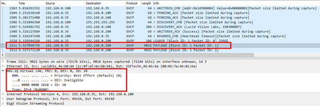
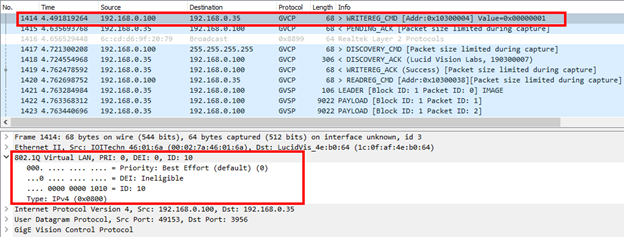
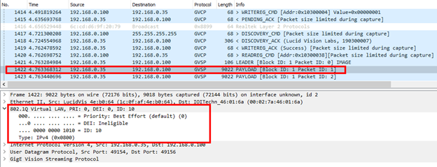
The 802.1Q standard was created to support VLANs. The network device that manages the VLAN (e.x. the switch) can apply a VLAN tag. The network ports that are part of the same VLAN can receive the VLAN-tagged traffic.

VLANs are identified by their VLAN ID, which can be a number from 1 to 4094:

The above trace shows a packet that has been tagged with VLAN ID 10.

Example Setup

Consider the following diagram using 2x Netgear GS305PP switches:

The diagram can be segmented into a VLAN with the following rules:

  1. The switch will tag any untagged traffic passing through Ports 1 or 5 with VLAN ID 10
  2. The switch will send traffic to ports that are part of the VLAN ID 10

In the above setup, traffic that arrives on Ports 2 to 4 will not be seen by the camera or the PC since those parts are not part of VLAN ID 10. This also means a device that connects to Ports 2 to 4 of either switch will not see traffic from the camera or the PC.

First Switch Setup

This switch has the following conditions:

  1. Traffic originating from the host PC is UNTAGGED
  2. Traffic entering Port 5 is TAGGED with VLAN ID 10
  3. Port 1 and Port 5 are part of VLAN ID 10
  4. Traffic received on Port 1 can be sent to Port 5 because they are part of VLAN ID 10

In the above setup, traffic that arrives on Ports 2 to 4 will not be seen by the camera or the PC since those parts are not part of VLAN ID 10. This also means a device that connects to Ports 2 to 4 of either switch will not see traffic from the camera or the PC.

Second Switch Setup

This switch has the following conditions:

  1. Traffic originating from the camera is UNTAGGED
  2. Traffic entering Port 1 is TAGGED with VLAN ID 10
  3. Port 1 and Port 5 are part of VLAN ID 10
  4. 4. Traffic received on Port 5 can be sent to Port 1 because they are part of VLAN ID 10

In the above setup, traffic that arrives on Ports 2 to 4 will not be seen by the camera or the PC since those parts are not part of VLAN ID 10. This also means a device that connects to Ports 2 to 4 of either switch will not see traffic from the camera or the PC.

Traffic Between Switches

This diagram has the following conditions:

  1. Traffic sent from Port 1 of the first switch to Port 5 of the second switch is already TAGGED
  2. Traffic sent from Port 5 of the second switch to Port 1 of the first switch is already TAGGED

In the above setup, traffic that arrives on Ports 2 to 4 will not be seen by the camera or the PC since those parts are not part of VLAN ID 10. This also means a device that connects to Ports 2 to 4 of either switch will not see traffic from the camera or the PC.

VLAN Setup on the Switches

The following steps show how to set up a VLAN on the Netgear GS305PP switch.

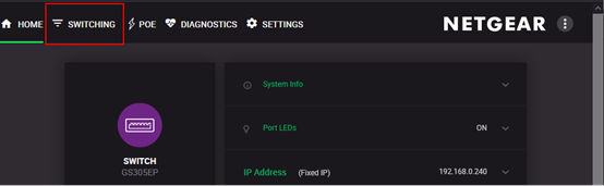
    1. Log into the Netgear switch
    2. Click Switching in the Netgear top menu bar
    3. Choose VLAN in the left menu bar
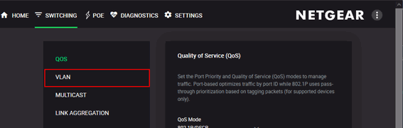
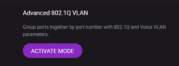
    4. Choose Advanced 802.1Q VLAN in the VLAN options and click the ACTIVATE MODE button
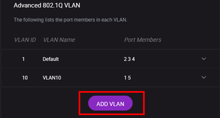
    5. Click ADD VLAN
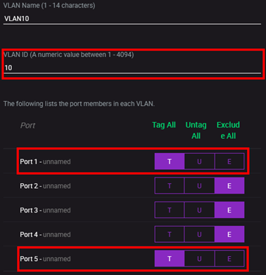
    6. Enter the VLAN details:
      • VLAN Name: VLAN10 (name of your choosing)
      • VLAN ID: 10
      • Set Port 1 and Port 5 to Tag All
      • Set Port 2, Port 3, and Port 4 to Exclude All (these ports will not be part of VLAN 10)
    7. Click Apply to save the VLAN details
    8. Click PVID Table to define the PVID of each port
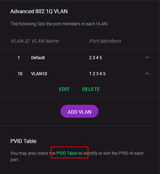
    9. Set the following PVID Table settings:
      • Port 1: VLAN ID 10
      • Port 5: VLAN ID 10

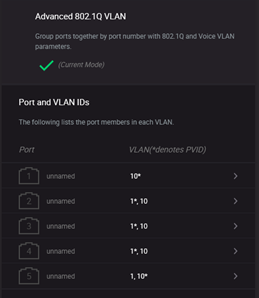
        This will assign Port 1 and Port 5 exclusively to VLAN ID 10.
    10. Apply the same rules to the second Netgear GS305PP switch

In the above setup, traffic that arrives on Ports 2 to 4 will not be seen by the camera or the PC since those parts are not part of VLAN ID 10. This also means a device that connects to Ports 2 to 4 of either switch will not see traffic from the camera or the PC.

Additional Setup Example

Consider the following diagram where VLAN ID 10 is assigned to Ports 1 and 5 of each switch:

This following conditions would apply:

    1. PC 1 will see traffic related to VLAN ID 10
    2. PC 1 WILL NOT see PC 2 or Camera 2 because Ports 3 and 4 are not part of VLAN ID 10
    3. PC 2 will see Camera 2
    4. PC 2 WILL NOT see PC 1 or Camera 1 because Ports 3 and 4 are not part of VLAN ID 10

In the above setup, traffic that arrives on Ports 2 to 4 will not be seen by the camera or the PC since those parts are not part of VLAN ID 10. This also means a device that connects to Ports 2 to 4 of either switch will not see traffic from the camera or the PC.

Was this helpful?

Yes  No
Related Articles
  • Using QOI with LUCID Cameras
  • Projecting a Helios2 3D image to and from a 2D image
  • Focusing a Triton2 EVS Camera
  • Controlling Triton2 EVS camera’s event rate when connected at less than 2.5GigE (Event Rate Control / ERC)
  • Solving driver-related RDMA streaming issues with Ubuntu 22.04
  • Using Multiple RDMA Cameras on a Switch

Didn't find your answer? Contact Us

  Using TCP with Atlas10 cameras on Linux

Using Multiple ROIs with LUCID Cameras  

© 2024 LUCID Vision Labs Inc.
Looking to purchase our cameras?
Visit the LUCID Webstore at thinklucid.com
LUCID Support & Help
Welcome to LUCID

We use cookies to facilitate online purchases and analyze our traffic. By clicking "Accept", you consent to our use of cookies.

Functional Always active
The technical storage or access is strictly necessary for the legitimate purpose of enabling the use of a specific service explicitly requested by the subscriber or user, or for the sole purpose of carrying out the transmission of a communication over an electronic communications network.
Preferences
The technical storage or access is necessary for the legitimate purpose of storing preferences that are not requested by the subscriber or user.
Statistics
The technical storage or access that is used exclusively for statistical purposes. The technical storage or access that is used exclusively for anonymous statistical purposes. Without a subpoena, voluntary compliance on the part of your Internet Service Provider, or additional records from a third party, information stored or retrieved for this purpose alone cannot usually be used to identify you.
Marketing
The technical storage or access is required to create user profiles to send advertising, or to track the user on a website or across several websites for similar marketing purposes.
Manage options Manage services Manage {vendor_count} vendors Read more about these purposes
View preferences
{title} {title} {title}