• Support Home
  • Getting Started
    • Connecting Your Camera
    • 3rd Party Software Getting Started Guides
  • Tech Ref Manuals
    • Arena SDK Documentation
    • HTP003S – Helios2+ ToF 3D
    • HLT003S – Helios2 ToF 3D
    • HLS003S – Helios ToF 3D
    • HLF003S – Helios Flex ToF 3D
    • ATX245S – Atlas10 24.5 MP
    • ATX204S – Atlas10 20.4 MP
    • ATX162S – Atlas10 16.2 MP
    • ATX124S – Atlas10 12.3 MP
    • ATX081S – Atlas10 8.1 MP
    • ATX051S – Atlas10 5.0 MP
    • ATL314S – Atlas 31.4 MP
    • ATL196S – Atlas 19.6 MP
    • ATL168S – Atlas 16.8 MP
    • ATL120S – Atlas 12.3 MP
    • ATL089S – Atlas 8.9 MP
    • ATL071S – Atlas 7.1 MP
    • ATL050S – Atlas 5.0 MP
    • ATL028S – Atlas 2.8 MP
    • ATP200S – Atlas IP67 20 MP
    • ATP120S – Atlas IP67 12.3 MP
    • ATP089S -Atlas IP67 8.9 MP
    • ATP071S – Atlas IP67 7.1 MP
    • ATP028S – Atlas IP67 2.8 MP
    • TRI200S – Triton 20.0 MP
    • TRI120S – Triton 12.3 MP
    • TRI122S – Triton 12.2 MP
    • TRI089S – Triton 8.9 MP
    • TRI071S – Triton 7.1 MP
    • TRI064S – Triton 6.3 MP
    • TRI054S – Triton 5.4 MP
    • TRI050S-P/Q – Triton 5.0 MP Polarized
    • TRI050S – Triton 5.0 MP
    • TRI032S – Triton 3.2 MP
    • TRI028S – Triton 2.8 MP
    • TRI023S – Triton 2.3 MP
    • TRI016S – Triton 1.6 MP
    • TRI005S – Triton 0.5 MP
    • TRI004S – Triton 0.4 MP
    • TRI02KA – Triton 2K Line Scan
    • PHX200S – Phoenix 20.0 MP
    • PHX120S – Phoenix 12.3 MP
    • PHX122S – Phoenix 12.2 MP
    • PHX089S – Phoenix 8.9 MP
    • PHX064S – Phoenix 6.3 MP
    • PHX050S-P/Q – Phoenix 5.0 MP Polarized
    • PHX050S – Phoenix 5.0 MP
    • PHX032S – Phoenix 3.2 MP
    • PHX023S – Phoenix 2.3 MP
    • PHX016S – Phoenix 1.6 MP
    • PHX004S – Phoenix 0.4 MP
  • Application Notes
    • Bandwidth Sharing in Multi-Camera Systems
    • Combine Helios 3D Point Cloud with RGB Color
    • I2C Support on LUCID Cameras
    • Using GPIO on LUCID Cameras
    • Using PTP & Scheduled Action Commands
    • Helios2 And Triton Synchronization
    • Product Change Notifications (PCN)
  • Knowledge Base
  • Contact Support
  • Log In
  • Support Home
  • Getting Started
    • Connecting Your Camera
    • 3rd Party Software Getting Started Guides
  • Tech Ref Manuals
    • Arena SDK Documentation
    • HTP003S – Helios2+ ToF 3D
    • HLT003S – Helios2 ToF 3D
    • HLS003S – Helios ToF 3D
    • HLF003S – Helios Flex ToF 3D
    • ATX245S – Atlas10 24.5 MP
    • ATX204S – Atlas10 20.4 MP
    • ATX162S – Atlas10 16.2 MP
    • ATX124S – Atlas10 12.3 MP
    • ATX081S – Atlas10 8.1 MP
    • ATX051S – Atlas10 5.0 MP
    • ATL314S – Atlas 31.4 MP
    • ATL196S – Atlas 19.6 MP
    • ATL168S – Atlas 16.8 MP
    • ATL120S – Atlas 12.3 MP
    • ATL089S – Atlas 8.9 MP
    • ATL071S – Atlas 7.1 MP
    • ATL050S – Atlas 5.0 MP
    • ATL028S – Atlas 2.8 MP
    • ATP200S – Atlas IP67 20 MP
    • ATP120S – Atlas IP67 12.3 MP
    • ATP089S -Atlas IP67 8.9 MP
    • ATP071S – Atlas IP67 7.1 MP
    • ATP028S – Atlas IP67 2.8 MP
    • TRI200S – Triton 20.0 MP
    • TRI120S – Triton 12.3 MP
    • TRI122S – Triton 12.2 MP
    • TRI089S – Triton 8.9 MP
    • TRI071S – Triton 7.1 MP
    • TRI064S – Triton 6.3 MP
    • TRI054S – Triton 5.4 MP
    • TRI050S-P/Q – Triton 5.0 MP Polarized
    • TRI050S – Triton 5.0 MP
    • TRI032S – Triton 3.2 MP
    • TRI028S – Triton 2.8 MP
    • TRI023S – Triton 2.3 MP
    • TRI016S – Triton 1.6 MP
    • TRI005S – Triton 0.5 MP
    • TRI004S – Triton 0.4 MP
    • TRI02KA – Triton 2K Line Scan
    • PHX200S – Phoenix 20.0 MP
    • PHX120S – Phoenix 12.3 MP
    • PHX122S – Phoenix 12.2 MP
    • PHX089S – Phoenix 8.9 MP
    • PHX064S – Phoenix 6.3 MP
    • PHX050S-P/Q – Phoenix 5.0 MP Polarized
    • PHX050S – Phoenix 5.0 MP
    • PHX032S – Phoenix 3.2 MP
    • PHX023S – Phoenix 2.3 MP
    • PHX016S – Phoenix 1.6 MP
    • PHX004S – Phoenix 0.4 MP
  • Application Notes
    • Bandwidth Sharing in Multi-Camera Systems
    • Combine Helios 3D Point Cloud with RGB Color
    • I2C Support on LUCID Cameras
    • Using GPIO on LUCID Cameras
    • Using PTP & Scheduled Action Commands
    • Helios2 And Triton Synchronization
    • Product Change Notifications (PCN)
  • Knowledge Base
  • Contact Support
  • Log In
home/Knowledge Base/Camera Features/Using LUCID’s TFL- and TFL-II Mount Adapters for EF Lenses

Using LUCID’s TFL- and TFL-II Mount Adapters for EF Lenses

2015 views 3 January 12, 2021 Updated on October 31, 2023

Introduction

The EF-Mount Lens to TFL-Mount Birger Adapter (ADA-TFL-EF-US/ADA-TFL-EF-EU) and EF-Mount Lens to TFL-II Mount Birger Adapter (ADA-TFL2-EF-US/ADA-TFL2-EF-EU)  with M8 GPIO camera connection and power supply provides the ability to use any Canon EF lens on the LUCID’s TFL-mount models and TFL-II mount models (Specific Atlas 5GigE models and Atlas10 10GigE models). The M8 connections allows the users to electronically focus the lens through serial commands. The following KB article will describe how to issue commands to control and focus an EF lens through the Birger adapter.

Function Summary

Using LUCID’s serial implementation, the non-opto isolated pins (Line 2 and Line 3 on Atlas) can be used to send commands to an EF lens controller to focus an EF lens.

Wiring Diagram

Equipment Used

  • ATL314S-CT 31MP IMX342 color (P/N: ATL314S-CT), contact Support for firmware
  • Birger TFL to EF mount adapter with GPIO adapter cable for Atlas (P/N: ADA-TFL-EF)
    The steps in this KB are also applicable to the Birger TFL-II to EF mount adatper with GPIO adapter cable
  • Arena SDK v1.0.28.3 or newer (Includes ArenaView)
  • Canon EF-S 18-55mm f/3.5-5.6 IS II or Canon EF-S 35mm f/2.8 Macro IS STM

Hardware Installation Instructions

  1. Connect Birger TFL to EF adapter to Atlas Camera
  2. Attach EF lens to Adapter
  3. Attach M12 cable to camera and PC
  4. Attach M8 cable from Birger to Atlas GPIO M8 port
  5. Plug in Birger power cord to power supply / outlet
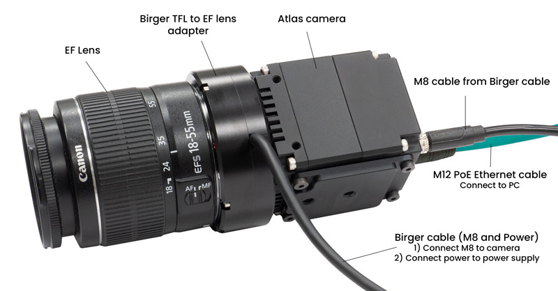
Birger EF Lens Adapter Layout

Table of Contents

Introduction
Function Summary
Equipment Used
Hardware Installation Instructions
Initial Camera Setup Using ArenaView
Focusing the Lens with Serial Write Commands
Learn Absolute Focus Range: la
Move Focus to Zero Position: mz
Set Current Focus Counter Position to Zero: sf0
Move Focus to Infinity Position: mi
Additional Commands
Reading the Serial Buffer
Arena SDK Example

Initial Camera Setup Using ArenaView

The Birger adpater uses the 15200-8N1 specification for serial communication:

  • 115200 baud rate | 8 data bits | No parity | 1 stop

Additional information about the Birger adapter and full list of serial commands/responses can be found at https://birger.com/download/

Download and install Arena SDK on the host PC.

After the Atlas camera, Birger adapter, and EF lens are put together and connected to the host PC, launch ArenaView. We will set the following Atlas parameters in ArenaView:

Step 1: Set Serial Baud Rate to Baud 115200.

Step 2: Set Serial Receive Source to Line 3.

Step 3: Set Line Selector to Line2.

Step 4: Set Line 2’s Line Mode to Output.

Step 5: Set Line 2’s Line Source to Serial Transmit.

Step 6: Set Line Selector to Line4.

Step 7: Set Line 4’s Voltage External Enable to True.

Focusing the Lens with Serial Write Commands

In this section we will be sending serial commands from the camera to the adapter to focus the lens. We can also read the response sent to the camera. This can be done by using Write and Read serial commands on the camera.

In ArenaView, press to capture continuous images.

Learn Absolute Focus Range: la

This command learns the focus range of the lens in a single step. No other lens movement commands can be issued while this command is in progress:

la <CR>

We will need to translate this command from ASCII to hex:

ASCII l a   <CR>
Hex 0x 6C 61 20 2D

The above command is 4 bytes.

Transmitting the ‘la’ Command with a serial write command

Step 1: Reset the Serial Access Buffer.

  • Set Serial Operation Selector to Reset
  • Click the Serial Operation Execute command

Step 2: Prepare the command to be transmitted.

  • Set Serial Operation Selector to Write
  • Enter 0x6C61202D in Serial Access Buffer
  • Set Serial Access Length to 4 to transmit 4 bytes

Step 3: Transmit the serial command.

  • Click the Serial Operation Execute command

Move Focus to Zero Position: mz

This command moves the lens focus to the zero position.

mz <CR>

We will need to translate this command from ASCII to hex:

ASCII m z   <CR>
Hex 0x 6D 7A 20 2D

The above command is 4 bytes.

Transmitting the ‘mz’ Command with a serial write command

Step 1: Reset the Serial Access Buffer.

  • Set Serial Operation Selector to Reset
  • Click the Serial Operation Execute command

Step 2: Prepare the command to be transmitted.

  • Set Serial Operation Selector to Write
  • Enter 0x6D7A200D in Serial Access Buffer
  • Set Serial Access Length to 4 to transmit 4 bytes

Step 3: Transmit the serial command.

  • Click the Serial Operation Execute command

Set Current Focus Counter Position to Zero: sf0

The sf command sets the current lens focus position with the value specified. When sending the mz command to move the focus to the zero position, the lens encoder position will typically be a non-zero value. Setting sf0 after moving the focus to the zero position allows you to mark this position as zero, which can then be used with the focus absolute command to return to the same zero position (fa 0).

sf0 <CR>

We will need to translate this command from ASCII to hex:

ASCII s f 0   <CR>
Hex 0x 73 66 30 20 2D

The above command is 5 bytes.

Transmitting the ‘sf0’ Command with a serial write command

Step 1: Reset the Serial Access Buffer.

  • Set Serial Operation Selector to Reset
  • Click the Serial Operation Execute command

Step 2: Prepare the command to be transmitted.

  • Set Serial Operation Selector to Write
  • Enter 0x736630200D in Serial Access Buffer
  • Set Serial Access Length to 5 to transmit 5 bytes

Step 3: Transmit the serial command.

  • Click the Serial Operation Execute command

Move Focus to Infinity Position: mi

This command moves the lens focus to the infinity position.

mi <CR>

We will need to translate this command from ASCII to hex:

ASCII m i   <CR>
Hex 0x 6D 69 20 2D

The above command is 4 bytes.

Transmitting the ‘mi’ Command with a serial write command

Step 1: Reset the Serial Access Buffer.

  • Set Serial Operation Selector to Reset
  • Click the Serial Operation Execute command

Step 2: Prepare the command to be transmitted.

  • Set Serial Operation Selector to Write
  • Enter 0x6D69200D in Serial Access Buffer
  • Set Serial Access Length to 4 to transmit 4 bytes

Step 3: Transmit the serial command.

  • Click the Serial Operation Execute command

Additional Commands

Command Description Hex Value Command Length
mf50 Move focus +50 counts 0x6D663530200D 6 bytes
mf-50 Move focus -50 counts 0x6D662D3530200D 7 bytes
fa2000 Move absolute focus to position 2000 0x666132303030200D 8 bytes

To confirm successful serial transmission, verify check the node Serial Operation Status = Success.

A full list of serial commands is available in the EF-232 User Manual available at https://birger.com/download/.

Reading the Serial Buffer

After transmitting a serial command to the adapter, it will send a response that can be read from the Serial Access Buffer.

Reading the Adapter Response in the Serial Access Buffer

Step 1: Verify Serial Operation Result = Success.

Step 2: Note the value in Serial Received Size.

Step 3: Set Serial Access Length to the value in Serial Received Size.

Step 4: Set Serial Operation Selector to Read.

Step 5: Click the Serial Operation Execute command.

The Serial Access Buffer will be filled with a value that can be translated from hex to ASCII.

0x6661313030200D4F4B0D444F4E453130302C300D

Translated:

Hex 0x 66 61 31 30 30 20 0D
ASCII f a 1 0 0   <CR>
Hex 0x 4F 4B 0D
ASCII O K <CR>
Hex 0x 44 4F 4E 45 31 30 30 2C 30 0D
ASCII D O N E 1 0 0 , 0 <CR>
66 61 31 30 30 20 0D
4F 4B 0D
44 4F 4E 45 31 30 30 2C 30 0D

Translated Response:

fa100 <CR>
OK<CR>
DONE100,0<CR>

See the adapter’s expected serial responses in the EF-232 User Manual available at https://birger.com/download/.

Arena SDK Example

LUCID currently offers an SDK example to provide basic focus functionality for the adapter. To download this example please contact support@thinklucid.com.

Was this helpful?

3 Yes  No
Related Articles
  • Using QOI with LUCID Cameras
  • Using Multiple Helios Cameras Simultaneously
  • Shading Correction Control (Atlas10)
  • Save Image on LUCID Camera’s File System
  • Multicast Device Discovery with LUCID Cameras
  • Comparing LUCID’s IMX490 Cameras: TRI054S vs. TDR054S with AltaView

Didn't find your answer? Contact Us

  Binning and Decimation on LUCID Cameras

Export Control of LUCID Products  

© 2024 LUCID Vision Labs Inc.
Looking to purchase our cameras?
Visit the LUCID Webstore at thinklucid.com
LUCID Support & Help
Welcome to LUCID

We use cookies to facilitate online purchases and analyze our traffic. By clicking "Accept", you consent to our use of cookies.

Functional Always active
The technical storage or access is strictly necessary for the legitimate purpose of enabling the use of a specific service explicitly requested by the subscriber or user, or for the sole purpose of carrying out the transmission of a communication over an electronic communications network.
Preferences
The technical storage or access is necessary for the legitimate purpose of storing preferences that are not requested by the subscriber or user.
Statistics
The technical storage or access that is used exclusively for statistical purposes. The technical storage or access that is used exclusively for anonymous statistical purposes. Without a subpoena, voluntary compliance on the part of your Internet Service Provider, or additional records from a third party, information stored or retrieved for this purpose alone cannot usually be used to identify you.
Marketing
The technical storage or access is required to create user profiles to send advertising, or to track the user on a website or across several websites for similar marketing purposes.
Manage options Manage services Manage {vendor_count} vendors Read more about these purposes
View preferences
{title} {title} {title}